
Message Ordering - Simple Case Study

In this note, I show how to guarantee a specific order for message arrival.
I supply working code in a repository for this example.
In this example, I imagine two components “A” and “B”, plus a third component which puts events in order for B.
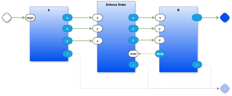
A has 3 outputs “x”, “y” and “z”.
B has 3 inputs, “x”, “y” and “z”.
B requires that the inputs arrive in a specific order. First “x”, then “y”, finally “z”. Once all 3 inputs arrive in the correct order, B executes some action. In practice, this kind of thing might be needed when supplying arguments to a component - send the arguments first, then ask the component to take action, akin to parameters to a function where the parameters are evaluated before the function is called.
In the function-based paradigm all arguments arrive simultaneously in a big block of data1, because the function-based paradigm makes the simplifying assumption that time (and order) does not matter. Implicit ordering of evaluation is generally avoided. When the pure function-based paradigm is applied to problems that do involve time, the result is wasted brain-power needed to devise work-arounds like futures, promises, control-flow operators (like && and ||), etc. These kinds of work-arounds are a tell that shows that something other than the function-based paradigm might be more suitable for expressing such problems and their solutions.
The idea of guaranteeing order of messages can be expressed in a straight-forward manner using 0D techniques. Basically, 0D is a way of totally isolating components from one another and of not placing arbitrary restrictions on their behaviours, e.g. routing and side-effects. 0D can be thought of as a combination of 2 simple kinds of components - Containers and Leaves. Leaves are, essentially, closures with 1 input queue and 1 output queue. Containers are compositions of Leaves and other Containers. Containers route messages between their children components. Containers can compose layers of components in a recursive manner to any depth. More detail about 0D can be found in other essays.
0D makes it possible to begin with simple components and to compose them, like LEGO® blocks, into useful solutions to specific problems.
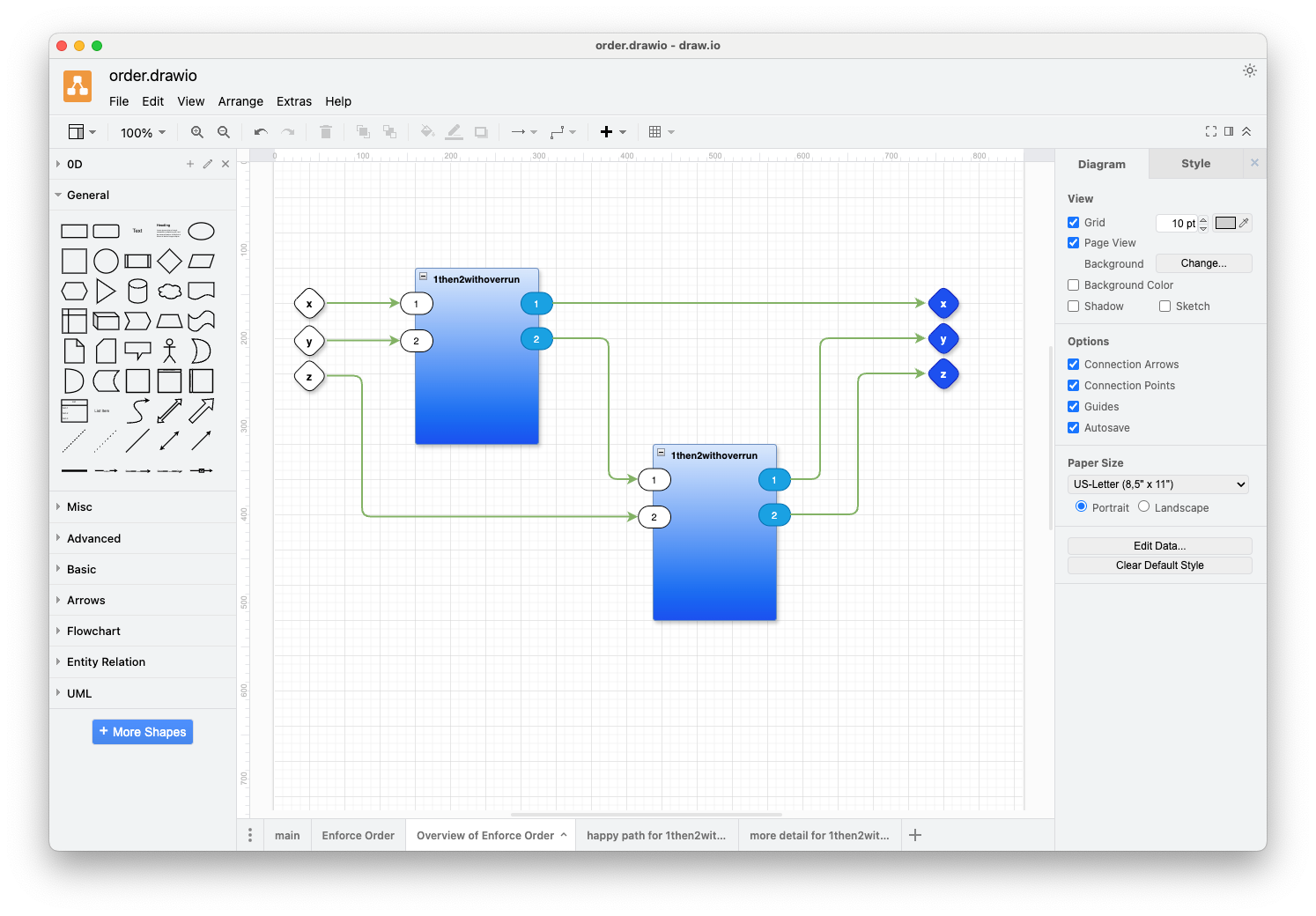
For this simple case study, we need to use a simple component called “1then2withoverrun”. We can cascade such simple components to form a network that guarantees the order of messages. Cascading is simplified because 0D components are highly decoupled and can be arranged in any order without affecting their behaviour.
We will create a dummy component - B - that accepts messages in a specific order, then announces success and quits. In more practical situations, such a receiving component would actually do something more interesting in response to the input messages.
In a sense, this example shows how to implement a behaviour which is often called “dataflow”. In “dataflow”, a component produces an action only when all inputs have arrived. As a simple example, an “addition” dataflow component sums its inputs only when all inputs have arrived, e.g. “result := b + c”. Using 0D techniques, we can simulate exactly this behaviour, as discussed in this note, but, it should be noted that 0D components do not inherently “wait” for inputs. A 0D component is woken for every input. It is the responsibility of the component to buffer messages if it needs to implement “dataflow” behaviour. In practice, “dataflow” behaviour tends not to be needed in many 0D applications, but, I’ll show how to accomplish this behaviour anyway.
Note, also, that the code described in this essay is very “low level”. Normally, programmers don’t need to code at this level - this is “systems programming”. Programmers can, instead, compose behaviours by using pre-built “low level” components such as those described herein.
The Limits of Function-Based Notation
The code in this example uses the Python language. Synchronous, function-based languages do not encourage simple 0D-like ideas. The concepts described herein look ugly and bulky when written out in a text-based, synchronous, function-based manner yet are straightforward when expressed differently. In this case, I use plain node-and-arrow diagrams and state diagrams to explain what is going on.
This example uses the draw.io2 editor for drawing diagrams of 0D components. Once draw.io and 0D are installed and running, it is much easier to use diagrams to express these ideas. The 0D “IDE” compiles diagrams to function-based code and runs it on existing computers. There are several versions of 0D. I use the Python version in this essay. Versions of 0D for Odin and Crystal exist. I imagine that it would be straight-forward to create versions of 0D for other languages, like WASM, Go, etc., but I haven’t done this yet (volunteers welcome).
In an ideal situation, we should have a single version of 0D expressed in a meta-language (a higher-than-high-level-language) which compiles to any existing 3GL language, e.g. to Python, to Go, to C, to Odin, to WASM, etc. A first step in this direction is my ongoing work on converting a Scheme program to Python by way of using a meta language.
1then2withoverrun
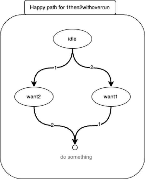
We begin with a simple 2-input, 3-output component called “1then2withoverrun”.
This component accepts messages on its input ports and outputs the messages in a specific order.
The main input ports are called “1” and “2”.
If it receives a message on port “1”, it then waits for another message on port “2”, then outputs both messages in the order “1” then “2”
On the other hand, if it receives a message on port “2”, it then waits for another message on port “1”, then outputs both messages in the order “1” then “2” (the same order as above).
By cascading this simple component, we can create circuits which handle incoming messages on more than 2 input pins and re-emits the messages in a given order.
We add 1 extra output pin to “1then2withoverrun” - an error port which signals the “overrun” condition. If the component receives a message on any pin other than the one it is waiting for, e.g. further inputs on “1” after it has received one “1” and is waiting for a “2”, it signals an “overrun” condition and resets itself.
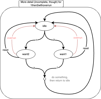
And, finally, we add one input pin, to allow a message to be sent to the component to reset it, making it begin waiting for inputs anew.
With added debugging, the final little network looks like:
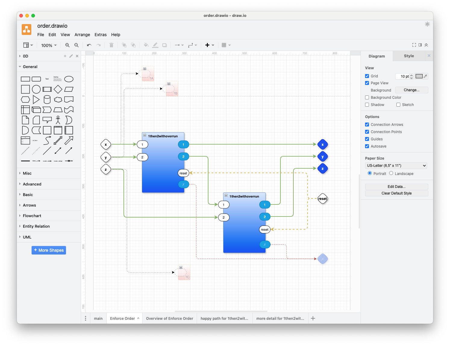
The above diagram includes 3 “probe” parts (the small red ones) to aid debugging during development. In this case, the probes show what inputs arrive in which order.
When we run the program, as shown above, we see the output:
... probe main.Enforce Order.?A₄: x
... probe main.Enforce Order.?C₃: z
... probe main.Enforce Order.?B₅: y
--- Outputs ---
⟪“”⦂“got x”⟫
⟪“”⦂“got y”⟫
⟪“”⦂“got z”⟫
⟪“”⦂“finished”⟫
The system creates a unique ID for each component. The first probe Component is called “main.Enforce Order.?A₄”. This naming indicates that the probe “?A” is tagged with a UID of “₄” and belongs to the component “Enforce Order” which, itself, belongs to the component “main”.
During development, a message is printed as a “port ⦂ message” pair, enclosed in Unicode brackets “⟪” ... ”⟫”. You can set options to strip most of the information and to display only the message content. This is the typical setting for a debugged and working application.
The printed output shows that messages arrived in the order “x”, then “z”, then “y”, but the messages were rearranged to be in the expected order “x”, then “y”, then “z”, all sent to the “” port. A final “finished” message is, also, sent to the “” port.
For simplicity, messages in this example are strings. In general, though, messages can contain data in any format.
Better Editor Needed
Adding more detail like reset and overrun control flow obfuscates the fundamental simplicity of the little network.
I think that I need a better editor. One which would allow me to put some arrows on different layers. Likewise, some of the ports could be put on different visual layers. You should be able to look at this diagram in terms of layers. For example, the arrows that are rendered as dotted lines, along with the ports that are associated with them, should be displayed only on more detailed layers. You should be able to look at a top-level layer that gives you an overview of the main control-flow of the design without seeing all of the other niggly details, like overrun error handling and reset handling. The draw.io editor does have layers, but I found this feature to be too difficult to use for programming.
In some sense, I want an eliding, markdown editor for diagrams. I want to mark ports and arrows with tags. I want an editor that lets me elide all graphical objects with certain tags or to elide all graphical objects above some certain tag level.
Github Repository
A working example of the above is in this repository:
https://github.com/guitarvydas/ordering
Run make.
Inspect the code by using draw.io (https://app.diagrams.net/) to open order.drawio.
It should be possible to fool around with the code by making changes to the diagrams on tabs main and Enforce Order.
This repository contains the 0D kernel written in Python.
See Also
References: https://guitarvydas.github.io/2024/01/06/References.html
Blog: https://guitarvydas.github.io/
Videos: https://www.youtube.com/@programmingsimplicity2980
Discord: https://discord.gg/Jjx62ypR
Leanpub: https://leanpub.com/u/paul-tarvydas
Gumroad:
https://tarvydas.gumroad.com
Twitter: @paul_tarvydas
The function-based notation makes it look like multiple arguments are being passed to functions, but this is just an optical illusion based on destructuring. In fact, Currying boils away multiple arguments and shows that functions take but 1 argument.
https://app.diagrams.net