
Example Message Flow

This note shows the message flow between two components A and B1.
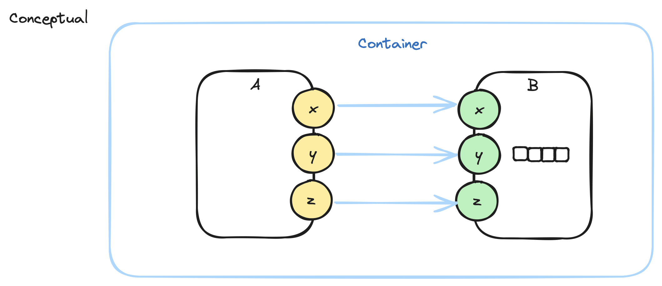
A has 3 outputs, x,y,z and sends messages to B, which has 3 inputs x,y,z.
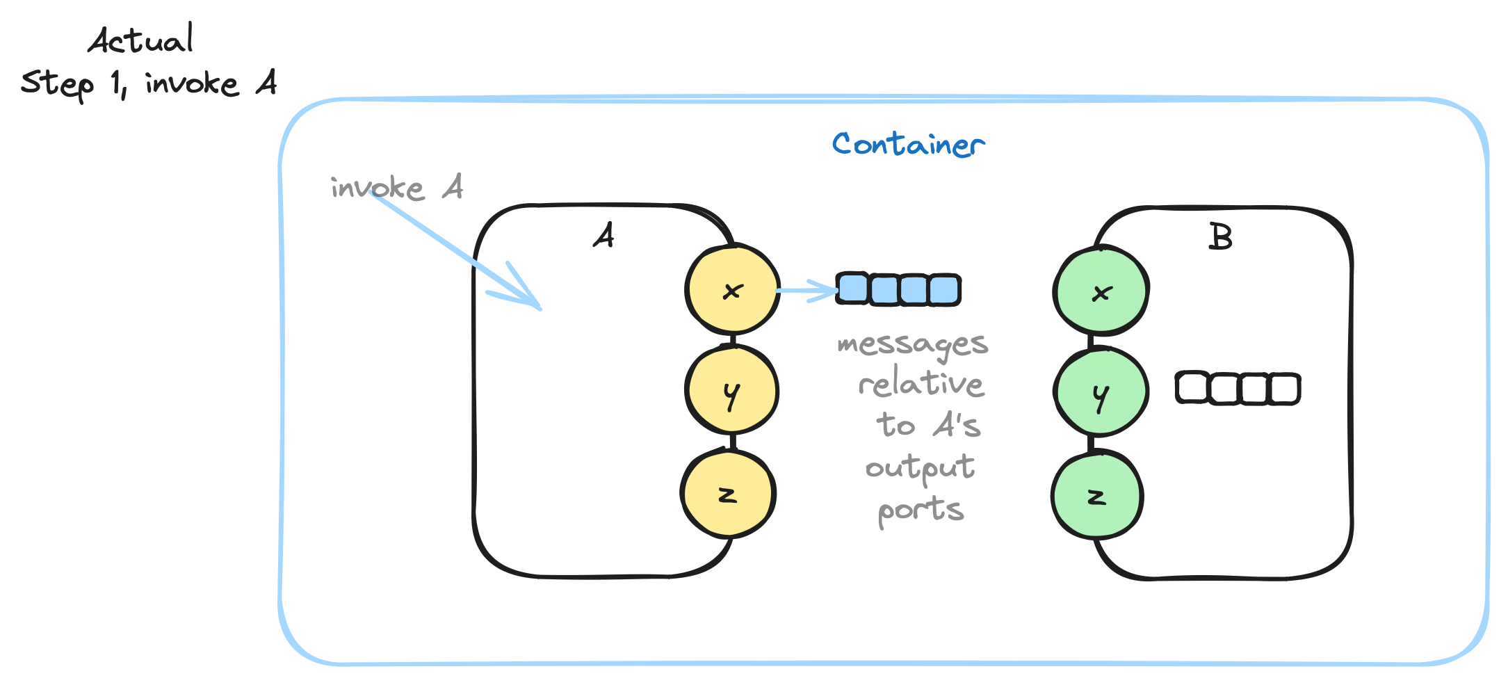
A cannot refer directly to B, so it leaves its outputs on an output queue for its parent to handle - the blue Container.
A - conceptually - has one output queue. All of A’s messages go to its queue, in order2.
When A is done, its Container picks up A’s output queue, and, routes the messages from A to B’s input.
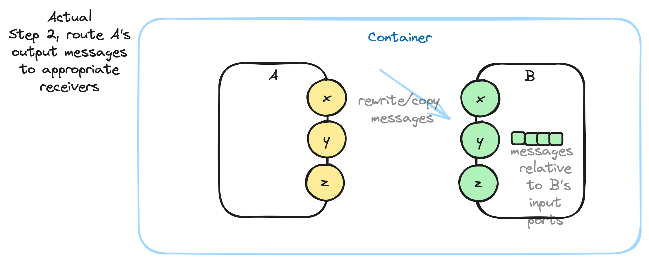
B has only one input queue. Messages are placed in B’s input queue in order. The parent Container routes messages atomically after running a child component.
During routing, the parent container copies and changes message ports from the sender’s output to the receiver’s input. In the above example, the output message with port A:x becomes a message to port B:x containing the same data as the original output message.
Aside: When implemented on an operating system, there is nothing more to do, since the Container gets atomic access to all of its children by virtue of running as a synchronous function on an operating system. On the other hand, if the implementation is on bare hardware, with no operating system, then semaphores must be used to guarantee atomic access to the appropriate queues. It is never possible to guarantee such atomic delivery in a truly distributed, asynchronous system, so, it behooves us to make the code for message delivery small and quick. In systems like the internet, all bets are off - you must devise protocols between the distributed devices for routing messages in the face of noticeable message delivery latencies.
Hardware circuits have the same problem. Every transistor and every integrated circuit is completely asynchronous. There is a minute, but, measurable latency between an input arriving at a port of an IC and an output generated in response. The latency is governed by the speed of light and the speed of electrons in the various oxides that make up the transistors and ICs. Hardware manufacturers provide data sheets which guarantee latencies and speeds. Designers must take such latencies into account when designing circuits.
What happens when A.x fires many messages quickly? A can fill up its own output queue and cause B’s input queue to become over-filled.
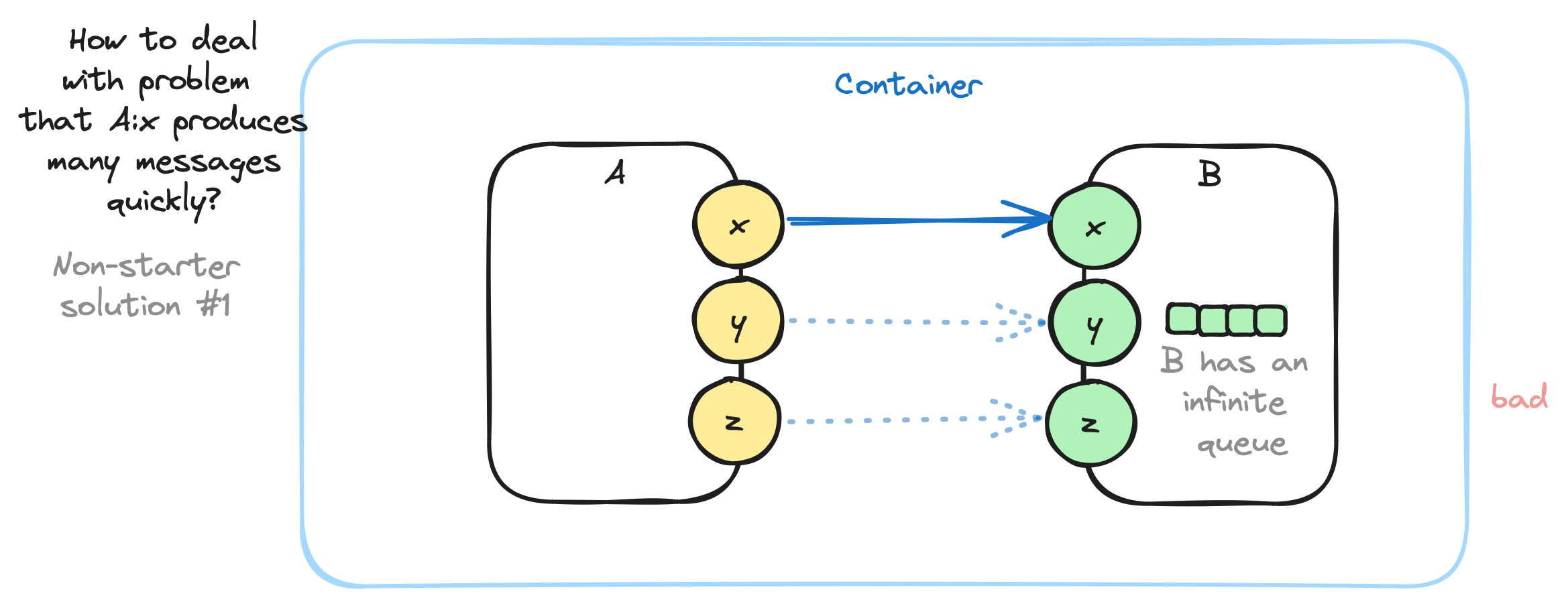
One answer is to imagine that B has an infinite queue. This works as long as B inhales and processes messages “fast enough”. This is possible if A fires messages in bursts, with some breathing time in between bursts, to let B process all of the messages. A lot of hardware designs work like this. Hardware engineers calculate the worst-case behaviour for specific instances of this kind of problem and pad their designs to fall well within acceptable boundaries. Many hardware ICs contain input queues of length 1, with a bit (called “overrun”) that gets set if an incoming message overwrites a previous message.
In some cases, this strategy does not work. For example, when A runs much faster than B, or when there just isn’t enough time for B to do enough work.
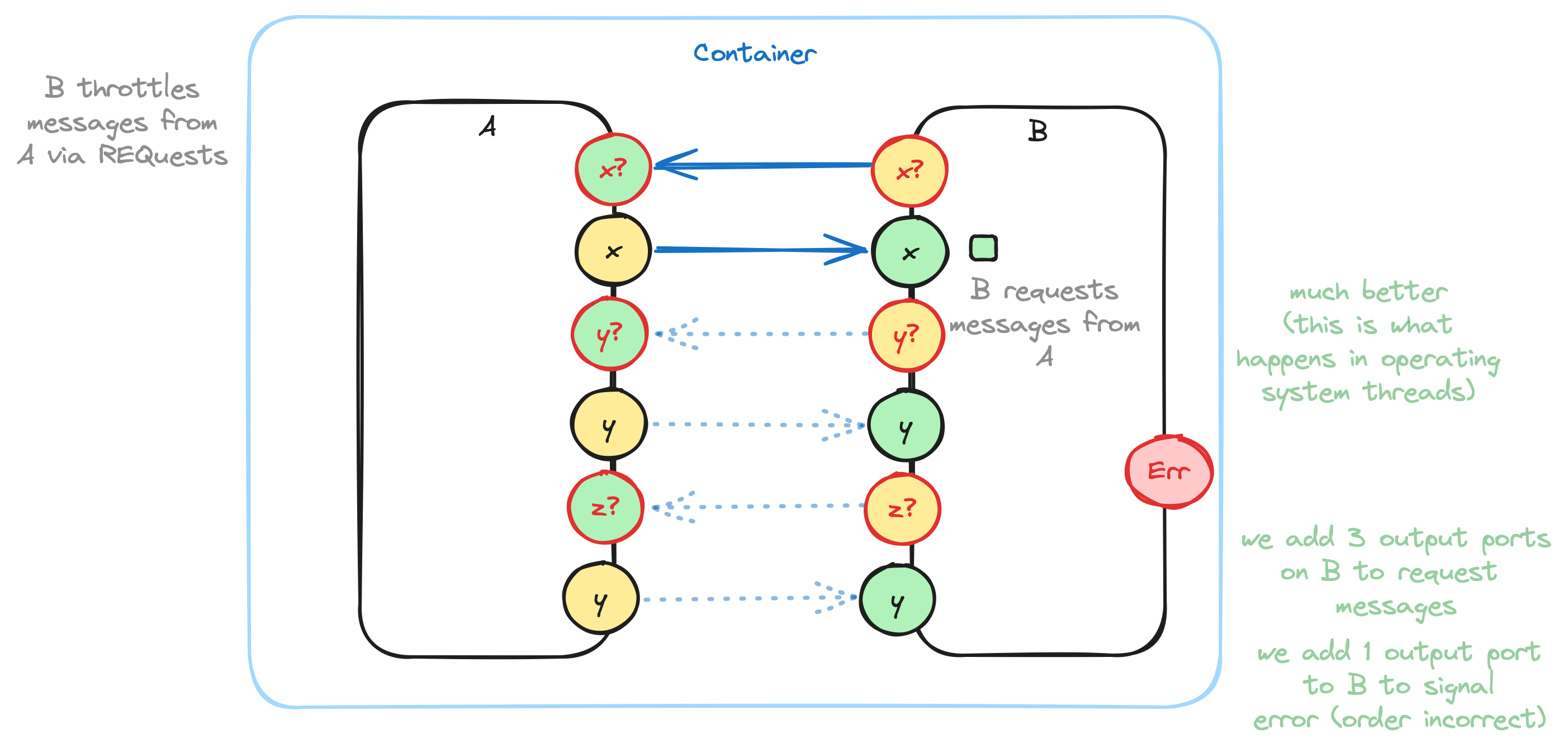
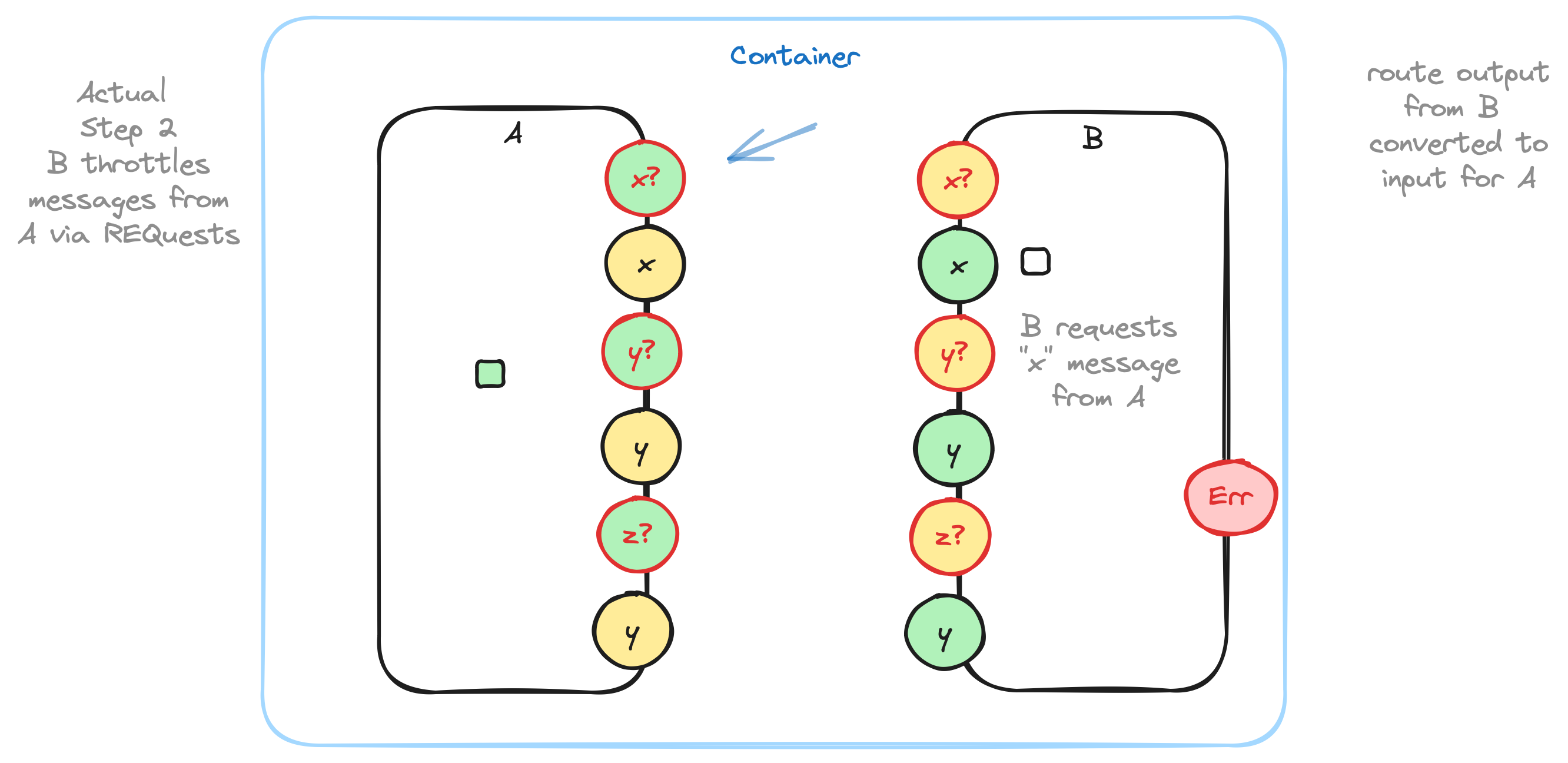
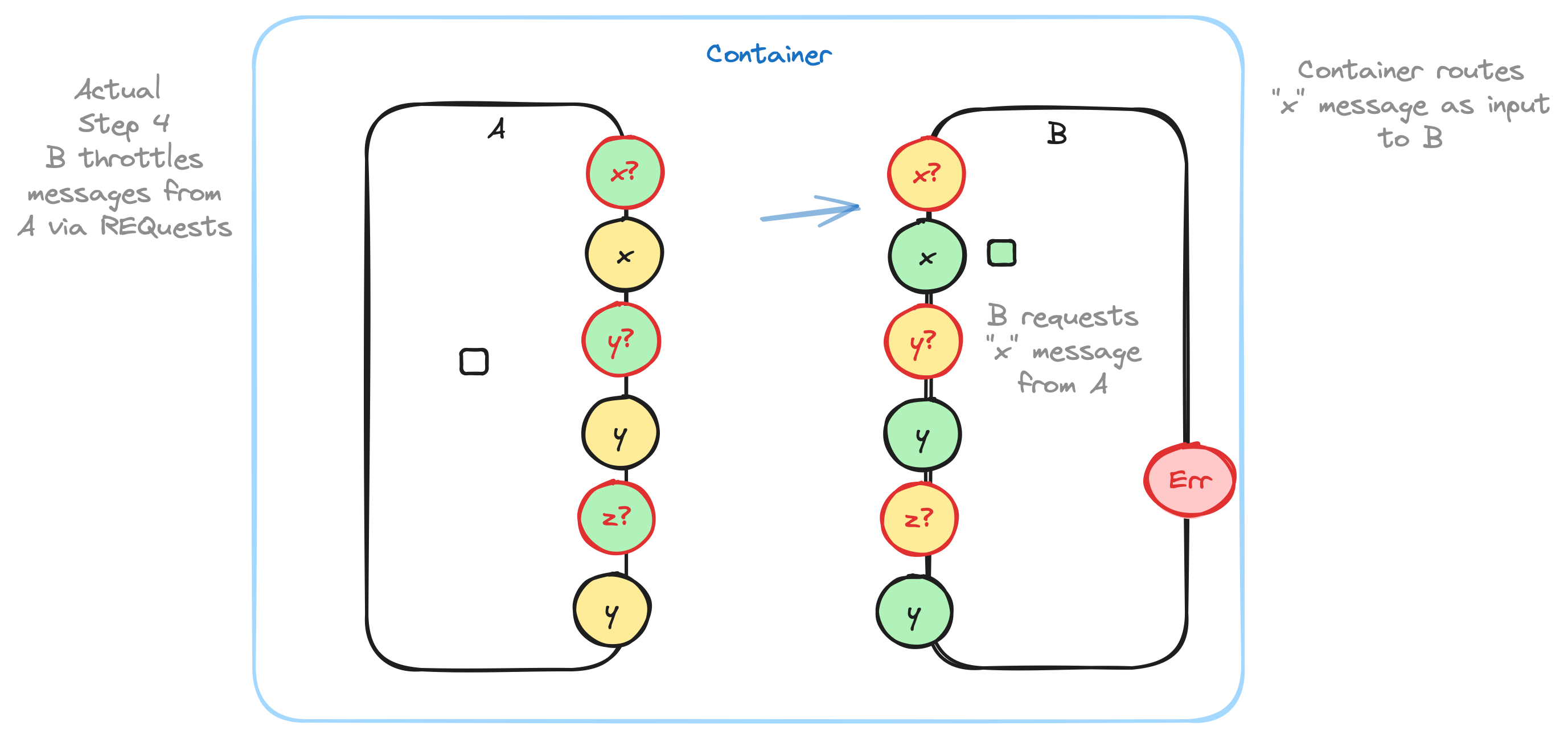
In such cases, engineers must implement control-flow protocols using a REQuest-RESPonse strategy. We see this kind of strategy used in terminal emulators, where control-S (^S) means “suspend, don’t send any more information” and control-Q (^Q) means “continue”. In this case, the computer hardware runs much faster than humans can read the information the screen, so the humans use the ^S-^Q protocol to throttle output from machines. Other approaches to this problem is the idea of using apps like “more” (called “less” in Linux) which do exactly the same kind of throttling by using the underlying operating system.
Operating systems implement control-flow protocols and hide this fact from users. Because operating systems are meant to be generalized, they need more software (i.e. operating systems are “less efficient” than specialized code) to handle all of the hoary edge-cases that might be encountered. Operating systems, also, try to optimize and hide control-flow protocols by using large buffers (e.g. several kilo-bytes) which lead to fewer context switches.
...
...
... and so on ...
Written out and diagrammed this way, this process looks quite inefficient, but, that’s how operating systems work under-the-hood. Operating systems use large buffers to minimize context switching.
There appears to be an extra level of indirection - leaving messages for the parent container to rewrite and route - but, that is how messages are delivered using file descriptors (FDs). A process “A” creates data and writes it to its stdout FD, which is then read in on stdin by process “B”.
Port IDs in the above map directly to FDs.
Arrows on the above diagram map to pipes in Unix processes. A pipe has one input and one output.
0D does one thing that is not supported by Unix. 0D allows fan-out. In effect, multiple processes can read from the same FD at the same time and get the same data. In Unix, only one process at a time can read from an FD. I.E. in Unix, a pipeline consists of one process which outputs on stdout and only one process which can read that output on its own stdin. In 0D, though, one process can output on stdout and multiple processes can read the output on their stdins. Fan-out can be optimized by using pointers and copy-on-write in cases where data copying is expensive, but, in a lot of cases, copying is not very expensive and can be simply implemented as copying. Note that pass-by-value in modern programming languages is essentially an inexpensive copy operation.
Fan-out and Abstraction and Single Input Queue
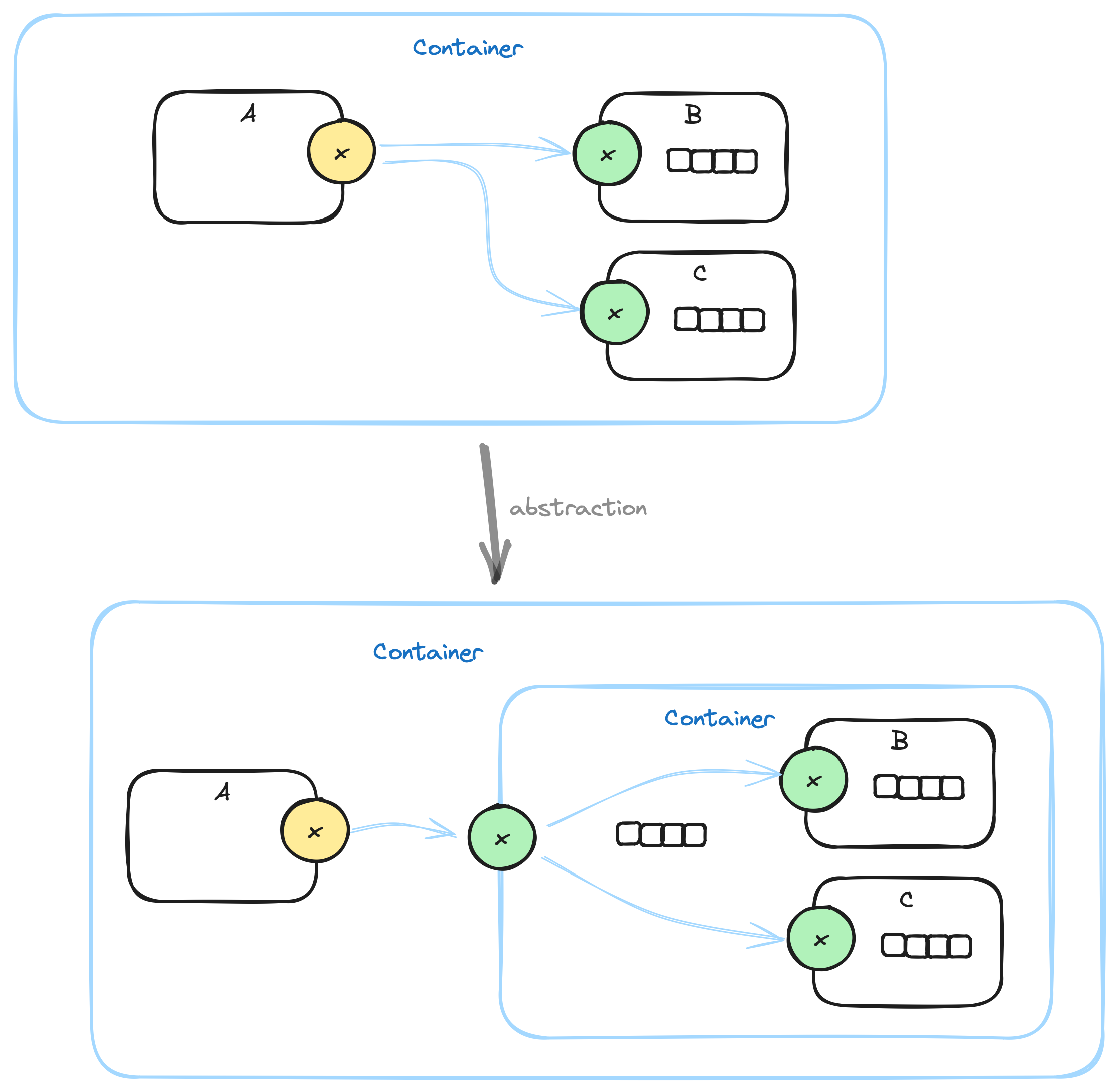
Fan-out is an essential element in abstraction.
Guaranteeing that each component has only one input queue is, also, essential to abstraction.
With fan-out, you can lasso several components and abstract the group as a single component, with fewer inputs as needed by the original group.
Abstraction is ambiguous with a one-queue-per-port strategy. Which component’s input queue do you use? Do you present all components’ input queues at the abstracted input? Does a container’s input queue become an array of queues? What if component “C” in the diagram has 3 input ports? How do those inputs get tied to inputs of the abstracted component? What if the input ports of component “C” have different names than the input ports of the abstracted container?
See Also
References: https://guitarvydas.github.io/2024/01/06/References.html
Blog: https://guitarvydas.github.io/
Videos: https://www.youtube.com/@programmingsimplicity2980
Discord: https://discord.gg/Jjx62ypR
Leanpub: https://leanpub.com/u/paul-tarvydas
Gumroad:
https://tarvydas.gumroad.com
Twitter: @paul_tarvydas
Thanks to Emil Valeev for prompting this discussion.
There is an obvious optimization here. Only one output queue is active at any one time, so the optimization is to use only one output queue, which the parent Container provides to A when it invokes A. Likewise with B. When A is finished, the parent empties all of the messages from the output queue and can re-use the same output queue for B’s output messages. But, it is easier to think of the output queue belonging to A and B.