
Towards PBP / 0D for Bash - Pond’ring Aloud
2025-03-20

What Does This Look Like When Written In Bash?
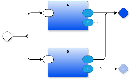
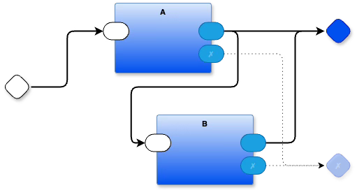
This diagram shows the composition of two Parts “A” and “B” (which could be the same Part, with the same name string, but two different positions / instantiations on the diagram).
Input mevents come in from the left-hand, white rhombus and split into 2 copies, one copy for the top part and one copy for the bottom part.
Each part processes the input at it’s own speed.
During processing, a part can generate multiple outputs over time. In this simple example, it looks like “A” produces one output and sends it to the output port named “”. If there’s an error during processing, a mevent might be send to the port named “✗”. It could be the case that “A” produces more that one output and sends each, one at a time to the “” output port.
The diagram doesn’t specify how many mevents are actually sent by “A” when it processes its input.
In fact, there is nothing that says that “A” produces any output at all. Maybe it just buffers incoming events and does something with them later.
The wires are just like empty pipes. Parts send mevents into the pipes like rolling little balls into the pipes. We don’t know if “A” sends only one little ball or many little balls into the output pipe through its output port “”. Likewise, we don’t know where the output, blue rhombus port will be connected. A programmer might connect the output to a Part that prints the mevents on a GUI, or, maybe the programmer will connect the output to a trash bin, discarding all outputs that are sent to the blue rhombus. Again, this diagram doesn’t specify. This diagram only shows how Parts are connected together in a little, reusable circuit.
Part “B” acts like Part “A”. It receives input and processes it, possibly producing outputs.
It might help to think about the Parts as separate computers. Say, “A” is an Arduino and “B” is a Raspberry Pi. The arrows are physical wires, or ethernet connections, or WIFI connections. Thinking about the above circuit in this way emphasizes the fact that the Parts are totally isolated from one another and the arrows are just data flow conduits.
Pond’ring Aloud
We already have the necessary technology to build these kinds of software circuits. A common technology might be UNIX® scripts. Another common technology involves a combination of closures and queue classes. A less-common technology is an experimental technology that I call 0D [Zero Dependencies] and have lately been calling PBP [Parts Based Programming].
An interesting question (but, not yet understood nor solved - comments requested) is “What would it take to make UNIX® processes into PBP / 0D?”
Thoughts...
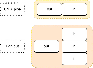
Fan-out, copying of input data to multiple FDs
Efficiency. Although, processes are fairly instant from a human’s perspective with modern hardware. Maybe efficiency is a continuum from “fast enough” to “very low-level fast”?
A syntax that doesn’t restrict one to thinking in only-linear-sequential terms and makes it convenient to talk about multiple inputs and multiple outputs.
Total isolation. Encapsulation of data is not enough. Control flow needs to be encapsulated, too.
Mevents instead of streams. [Mevent = a packet of data sent as an event. Much like asynchronous message sending, but it is valid to have a packet that contains no data (a “Bang” (called “edge-triggered” in electronics circles)].
Feedback loops.
Queues. FIFO queues instead of LIFO stacks-and-recursion.
Nested composition of Parts.
UNIX already has:
Isolation. Processes isolate data and control flow.
Multiple inputs and multiple outputs that accept / send data over time. At a low level, processes have multiple FDs. These are ports. The shell provides a pipe syntax (“|”) which connects output ports to input ports of process when they are created. Unfortunately, the textual syntax of the shell (/bin/sh, /bin/bash, /bin/zsh, etc.) makes it uncomfortable to use many ports. The shell provides easy access to stdin, stdout and stderr - only 3 of the many possible ports - but, describing many connections between other ports tends to result in unreadable code. A linear (textual) syntax does not lend itself to communicating interesting graph structures nor feedback loops, etc.
It is possible to create feedback loops, but, I’m unaware of any pipeline syntax that makes this easy and natural.
Queues. UNIX processes communicate through pipes via buffered queues. There are other ways to allow processes to communicate (e.g. mmap() and signals), but, we can ignore those.
Nested composition. Bash scripts can call other shell scripts, recursively, or they can call atomic commands.
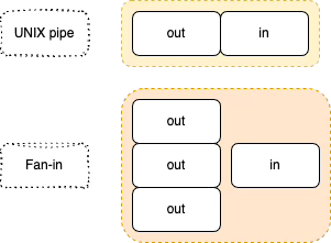
Fan-out and fan-in.
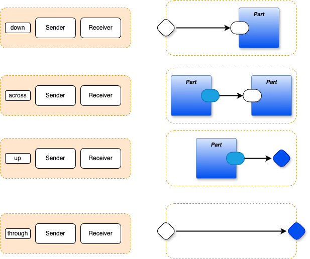
PBP connections are triples, to allow for nested composition of Parts.
But,
UNIX has no fan-out. One UNIX pipe cannot feed more than one input. To get full advantage of PBP, you need to allow one output mevent to be sent to two (or more) inputs.
No syntax beyond shell scripts. Line-oriented syntax encourages one to avoid multiple ports. This a major psychological effect / setback
UNIX works on streams of characters, not mevents. Mevent packets can easily be created by using bursty streams, or, data packets sent to sockets.
Potential answers / ideas:
A “tee”-like program written to output to 2 FDs (is that what ‘tee’ already does?)
draw.io to bash transpiler [We already have draw.io to Python/Odin/Javascript/CommonLisp, so this isn’t hard to imagine].
XML-ish “elements”, bracketed with strongly-typed brackets (<xyz> ... </xyz>), or, just JSON “objects” as mevents
Efficiency - It is unnecessary to engage in premature optimization (i.e. developing 0D the way I have been doing (I don’t need to listen to my own advice)). Get it working first, then, if it is good, someone will make it better. This happened to FP, Lisp, JS, etc. In the 1980s, FP was considered to be laughably inefficient.
I think that fan-in (multiple output ports feeding one input port) is possible using named pipes or by fiddling with FDs at a low level.
Order of Execution
The above diagram does not specify an order of execution for the Parts. Maybe the Parts run in “A” then “B” order, or, maybe they run in “B” then “A” order.
The diagram only guarantees that “A” and “B” finish processing before the output gate of the diagram (the blue rhombus) is valid and can be consumed. All mevents sent to the output gate are kept in a queue in order of arrival. The contents of the queue are not released until all of the internal Parts (in this case “A” and “B”) have finished their processing of any single mevent that arrived on the input gate (the white rhombus).
If more than one input mevent arrives, the first mevent is processed to completion by the innards of the diagram (in this case “A” and “B”) before the next mevent is processed, and so on. Each input mevent is processed to completion before another input mevent is consumed.
The Software Architect must specify execution order if that is important to the design of the system. The underlying system does not specify default behaviour that imparts any hidden meaning to the diagrams. The goal is to allow Software Architects to build custom solutions for any problem with the small set of operations made available.
If a Software Architect does want to specify order of execution, at least two idioms are possible.
One way is to send the first input only to “A”, then wire the output of “A” to, both, the input of “B” and the “” output gate.
This approach will make a copy of the output of “A”. If “B” does not need the data from the original input, i.e. “B” treats the input as a data-less event Bang. Or, if enough data can be found in the output of “A”, then this approach will work, triggering “B” into action only after “A” has finished and sent one mevent out of its “” port. [Aside, if “A” encounters an error and sends only a single mevent to its “✗” port, then “B” will not be triggered into action. In other programming languages, this kind of thing is handled by fooling with the control flow, i.e. by using try/catch. In this DPL (Diagrammatic Programming Language), exceptions are just mevents and exception handling can be done differently].
Another way might be to use a sequencer Part which guarantees ordering.
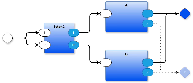
I’ve called this Part “1then2”.
The input from the left input gate is split into two and both copies are delivered to the “1then2” Part, in any order. Regardless of order of arrival, the data on input port “1” is always forwarded before the data arriving on input port “2”. For example, if data arrives “X” on input port “1” then “Y” on input port “2”, the output will be “X” on output port “1” then “Y” on output port “2”. If, on the other hand, data arrives “Y” on input port “2” then “X” on input port “1”, the output is the same: “X” on output port “1” then “Y” on output port “2”. Implementation of a “1then2” Part is only some 40 lines of Javascript (written for clarity, using more LOC than would be used normally).
See Also
Email: ptcomputingsimplicity@gmail.com
References: https://guitarvydas.github.io/2024/01/06/References.html
Blog: guitarvydas.github.io
Videos: https://www.youtube.com/@programmingsimplicity2980
Discord: https://discord.gg/65YZUh6Jpq
Leanpub: [WIP] https://leanpub.com/u/paul-tarvydas
Gumroad: tarvydas.gumroad.com
Twitter: @paul_tarvydas
Substack: paultarvydas.substack.com