
On Structured Message Passing
2025-02-02

In 1972, Atari produced a game called “Pong”. The design of the game was based solely on the use of available chips, but, contained no CPU nor program code.
I’ve included the schematic for this game below, from the website https://archive.org/details/pongschematics/mode/1up?view=theater.
Fig. 1 1972 Atari Pong Circuit
The first thing you notice, is that the schematic is a mess of detail. You have to know how to read electrical schematics to understand what is going on. This is no different from the need to understand programming languages to read modern program code that implements the same game.
Someone took the time to reverse-engineer what’s going on in this schematic and colourized it into some 15 groupings, as seen in Fig 2. This still doesn’t get rid of the need to know how to read schematics, but, at least shows that the design can be chunked and understood in smaller pieces.
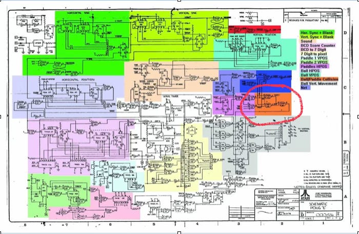
Fig. 2 Colourized Atari Pong Circuit
I’ve circled a tiny portion of the circuit for this discussion.
Imagine that the circled portion is wildly more complicated. To keep things simple in this example, we’ll simply ignore the fact that the circled portion contains only a few logic gates.
Can we replace the “Ball/Paddle Collision” - orange - block by another piece of circuitry? Yes. In software, that’s called “referential transparency”. In hardware, it’s called “pin-for-pin compatibility”.
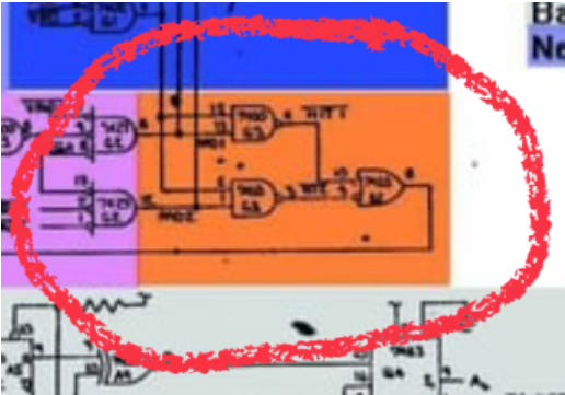
Fig. 3 Ball / Paddle Collision Detector
The orange sub-section has 3 inputs and one output. We can redraw it in outline form, as in Fig. 4.
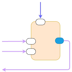
Fig. 4 Abstracted Ball / Paddle Collision Detector
The two inputs from the left are from the purple section.
Another input comes from the blue section above. How did I know? I know how to read schematics and I see that the left-most of the 3 lines that cross between the orange and blue sections feeds an input of the lower logic gate (a NAND gate, I can’t read the name of that gate, because of the poor resolution of this image)
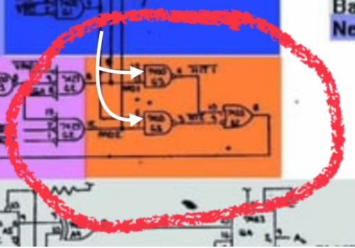
Fig. 5 Inputs Flowing from Blue Section into Orange Section
I’ve marked the input from the upper blue section with white arrows in Fig. 5.
There are two other taps that flow from the left purple section into the blue section via the orange section. They don’t actually belong to the orange section, but, that’s the way the schematic is drawn. Complain to the draftsperson or architect.
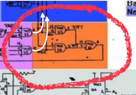
Fig. 6 Flow-Through Wires from Purple Section to Blue Section Via Orange Section
I’ve marked those flow-through wires in white on Fig. 6.
When we redraw the diagram as Fig. 4, we see that this sub-section of circuitry is quite simple to understand. It takes 3 inputs and produces 1 output. The output flow is shown in Fig. 7.
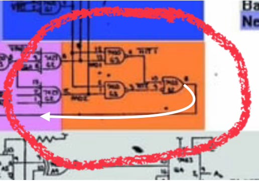
Fig. 7 Output
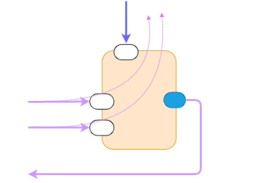
Fig. 8 - Duplicate of Fig 4, With Flow-Throughs Shown
I’ve duplicated Fig. 4, again, in Fig. 8, showing the flow-throughs from the purple section to the blue section.
You can see that the flow-throughs are “unstructured” and make the schematic diagram look more complicated than it needs to be.
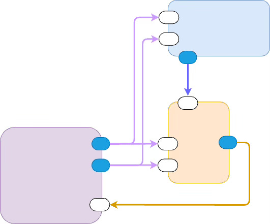
Fig. 9 - Redrawn with No Flow-Through Arrows
In Fig. 9, I’ve redrawn the circled area and have moved the flow-through wires outside of the orange box.
The circuit is still complicated, but, it is more “structured”. We don’t need to know what’s inside the orange and blue and purple sections. It is enough to know what their input and output APIs are and how they are wired together.
Structured Message Passing
We can use this same style of wiring for constructing software systems.
The rectangles must be concurrent and must be totally isolated from one another. The arrows represent one-way data flow - bereft of control flow.
FP - Functional Programming - discourages this kind of structuring. When a function calls another function, the caller function waits (“blocks”) until the callee returns a value. This means that the rectangles are not independent, and, that the wires represent 2-way data flow + control flow. A function call passes data and it passes control flow. In essence a function call says “here’s some data, calculate with it, then return a value to me - I’ll wait for you to finish”. Fig. 9 does not imply these kinds of flows.
See Also
References: https://guitarvydas.github.io/2024/01/06/References.html
Blog: guitarvydas.github.io
Videos: https://www.youtube.com/@programmingsimplicity2980
Discord: https://discord.gg/65YZUh6Jpq
Leanpub: [WIP] https://leanpub.com/u/paul-tarvydas
Gumroad: tarvydas.gumroad.com
Twitter: @paul_tarvydas
Substack: paultarvydas.substack.com