
Drafting Rules for Node-and-Wire Diagrams
2026-03-26

TL;DR
Several rules for readable node-and-wire DPL diagrams. The underlying constraint: diagrams earn their place only where text fails.
L;R
DPL
DPL stands for Diagrammatic Programming Language.
Use diagrams where text fails, and vice versa
Diagrams and text are complementary, not competing. Use diagrams for topology — what connects to what. Use text for logic and annotation. Neither is universal; both are necessary.
It is worth noting that SVG, for instance, treats rectangular figures and figures containing text as peers at the same structural level — the underlying representation does not privilege one over the other, which is exactly the right default.
No diagram should look complicated at first glance
Complexity hides in layers. Each layer must be independently legible without forcing the reader to confront detail they haven’t asked for — while still providing that detail elsewhere, so that the complete system loses nothing overall. The reader pulls detail on demand; the diagram does not push it. This requires async, message-passing architecture: synchronous/sequential languages cannot produce genuinely independent layers without incurring extra work. Implicit layering in a synchronous system is a polite fiction.
Components may have multiple input ports and multiple output ports
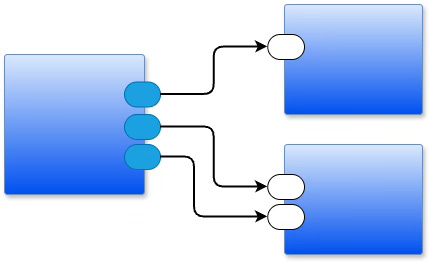
A node is not limited to one wire in and one wire out. Ports are named and positioned on the edges of a box. Multiple inputs arrive independently; multiple outputs depart independently.
Fan-out
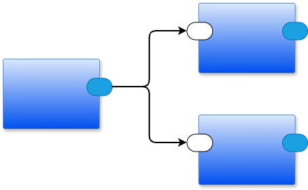
Fan-out — one output port wired to multiple downstream components — is natural in a node-and-wire diagram. The functional programming paradigm discourages it, because in software, fan-out requires copying values and subsequent garbage collection. In a message-passing system, the cost is explicit and the copies are intentional.
Fan-in
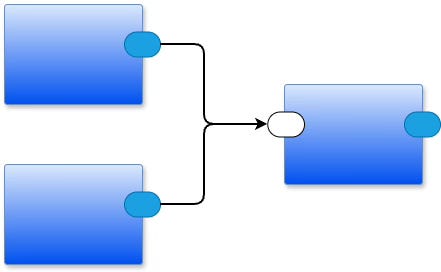
Fan-in — multiple upstream components wired to one input port — looks the same in both paradigms but behaves very differently. In a message-passing system, each arriving message drops into the receiver’s input queue in order of arrival; the receiver processes them in turn, and senders do not wait. In a function-call system, multiple callers sharing a single callee only look like fan-in: it is actually serialized, synchronous access — each caller blocks until the callee finishes before the next caller can proceed.
Feedback is a first-class citizen
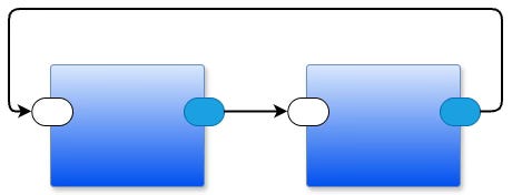
A wire that loops back — from a downstream component to an upstream one — is not a special case. It is a normal connection, drawn with the same right-angle routing as any other wire. Feedback is how systems remember, regulate, and adapt.
Feedback is not the same as recursion, and the difference matters. Imagine a line of people waiting at a ticket window. Feedback sends a person to the back of the line — they wait their turn. Recursion sends a person to the front, cutting in ahead of everyone else. In software terms: feedback drops a message into a queue and returns immediately; recursion suspends the current call and demands an answer before continuing. One is async and non-blocking; the other is sync and stack-consuming.
Let the compiler determine meaning from context — minimize symbol decoration
The IEC eventually replaced the zigzag resistor symbol with a plain rectangle. The zigzag was a pictogram of the physical component’s wound-wire construction — a piece of historical baggage baked into the notation. A labeled rectangle is cleaner, and the label carries all the semantic weight needed.
The same principle applies to software diagrams. In most popular programming languages, an identifier carries no visible decoration indicating whether it names a variable, a parameter, a function, a type, or something else — the compiler resolves that from context. A node-and-wire diagram can work the same way: use the smallest possible set of shapes, and let position, port names, and wiring topology convey meaning. Every additional symbol variant — every special shape that encodes a semantic distinction — is a vocabulary item the reader must memorize. Prefer one symbol with annotations over two symbols with implicit meanings.
Lines do not cross box boundaries
A line crossing a box boundary is two lines with a hidden junction at the edge. Make that explicit: ports are visible marks on a box’s edges. Crossing a boundary without a named port silently destroys layer independence.
Right-angle lines only; no crossings
Rounded right-angle bends. No crossing lines. No free-form curves. The diagram compiler only needs to know which port connects to which port — it does not care where on a box’s edge a port sits. So: move ports freely along edges to eliminate crossings. The result is visually cleaner, and the semantics are identical.
See Also
Email: ptcomputingsimplicity@gmail.com
Substack: paultarvydas.substack.com
Videos: https://www.youtube.com/@programmingsimplicity2980
Discord: https://discord.gg/65YZUh6Jpq
Leanpub: [WIP] https://leanpub.com/u/paul-tarvydas
Twitter: @paul_tarvydas
Bluesky: @paultarvydas.bsky.social
Mastodon: @paultarvydas
(earlier) Blog: guitarvydas.github.io
References: https://guitarvydas.github.io/2024/01/06/References.html